- 您现在的位置:买卖IC网 > Sheet目录341 > MAX8647ETE+T (Maxim Integrated)IC LED DRVR WT/RGB BCKLGT 16TQFN
�� �
�
�Ultra-Efficient� Charge� Pumps� for�
�Six� White/RGB� LEDs� in� 3mm� x� 3mm� Thin� QFN�
�Detailed� Description�
�The� MAX8647/MAX8648� have� an� inverting� charge�
�pump� and� six� current� regulators� capable� of� 24mA� each�
�to� drive� six� white� LEDs� or� two� sets� of� RGB� LEDs.� The�
�current� regulators� are� matched� to� within� ±0.4%� (typ)�
�providing� uniform� white� LED� brightness� for� LCD� back-�
�light� applications.� To� maximize� efficiency,� the� current�
�regulators� operate� with� as� little� as� 0.15V� voltage� drop.�
�Individual� white� LED� current� regulators� conduct� current�
�to� GND� or� NEG� to� extend� usable� battery� life.� In� the�
�case� of� mismatched� forward� voltage� of� white� LEDs,�
�only� the� white� LEDs� requiring� higher� voltage� are�
�switched� to� pull� current� to� NEG� instead� of� GND,� further�
�raising� efficiency� and� reducing� battery� current� drain.�
�Current-Regulator� Switchover�
�When� V� IN� is� higher� than� the� forward� voltage� of� the�
�white� LED� plus� the� 0.15V� headroom� of� the� current� regu-�
�lator,� the� LED� current� returns� through� GND.� If� this� con-�
�dition� is� satisfied� for� all� six� white� LEDs,� the� charge�
�pump� remains� inactive.� When� the� input� voltage� drops�
�so� that� the� current-regulator� headroom� cannot� be� main-�
�tained� for� any� of� the� individual� white� LEDs,� the� inverting�
�charge� pump� activates� and� generates� a� voltage� on� the�
�NEG� pin� that� is� no� greater� than� 5V� below� V� IN� .� Each� cur-�
�rent� regulator� contains� circuitry� that� detects� when� it� is�
�in� dropout� and� switches� that� current-regulator� return�
�path� from� GND� to� NEG.� Since� this� is� done� on� an� LED-�
�by-LED� basis,� the� LED� current� is� switched� for� only� the�
�individual� LED� requiring� higher� voltage,� thus� minimizing�
�power� consumption.�
�Low� LED� Current� Levels�
�The� MAX8647/MAX8648� internally� generate� a� PWM� sig-�
�used.� Figure� 2� shows� a� timing� diagram� for� the� I� 2� C� pro-�
�tocol.� The� MAX8647� is� a� slave-only� device,� relying�
�upon� a� master� to� generate� a� clock� signal.� The� master�
�(typically� a� microprocessor)� initiates� data� transfer� on�
�the� bus� and� generates� SCL� to� permit� data� transfer.� A�
�master� device� communicates� with� the� MAX8647� by�
�transmitting� the� proper� 8-bit� address� (0x9A)� followed�
�by� the� 8-bit� control� byte.� Each� 8-bit� control� byte� con-�
�sists� of� a� 3-bit� command� code� and� 5� bits� of� data� (Table�
�1).� Each� transmit� sequence� is� framed� by� a� START� (A)�
�condition� and� a� STOP� (L)� condition� (Figure� 2).� Each�
�word� transmitted� over� the� bus� is� 8� bits� long� and� is�
�always� followed� by� an� ACKNOWLEDGE� CLOCK�
�PULSE� (K).� The� power-on� default� settings� for� D4� to� D0�
�are� all� 0,� which� indicates� that� all� LED_� are� off.�
�Serial-Pulse� Dimming� Control� (MAX8648)�
�When� the� LEDs� are� enabled� by� driving� EN_� high,� the�
�MAX8648� ramps� LED� current� to� 24mA.� Dim� the� LEDs�
�by� pulsing� EN_� low� (1μs� to� 500μs� pulse� width).� Each�
�pulse� reduces� the� LED� current� based� on� the� LED� dim-�
�ming� table,� Table� 3.� After� the� current� reaches� 0.1mA,�
�the� next� pulse� restores� the� current� to� 24mA.� Figure� 3�
�shows� a� timing� diagram� for� EN_.� ENA� controls� LED1,�
�LED2,� and� LED3.� ENB� controls� LED4� and� LED5.� ENC�
�controls� LED6.�
�If� dimming� control� is� not� required,� EN_� work� as� simple�
�100%� brightness� or� off� controls.� Drive� EN_� high� to� enable�
�the� LEDs,� or� drive� EN_� low� to� disable.� The� IC� is� shut-�
�down� when� all� three� EN_� are� low� for� 4ms� or� longer.�
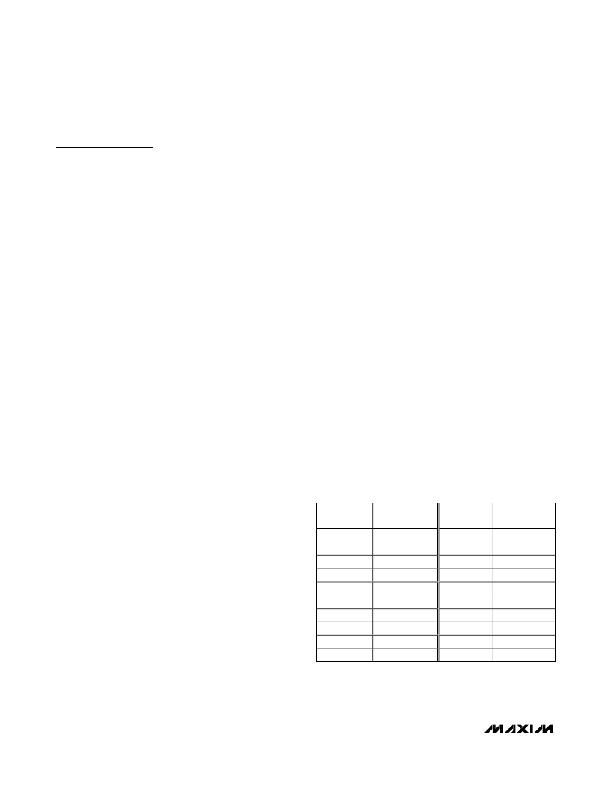
�Table� 1.� Internal� PWM� Duty� Cycle� vs.� LED�
�Set� Current�
�nal� to� obtain� higher� resolution� at� lower� currents.� See�
�Single-Wire� Pulse� Dimming� in� the� Typical� Operating�
�Characteristics� section.� As� the� I� LED� setting� is� below�
�6.4mA,� the� IC� adjusts� not� only� I� LED� DC� current,� but� the�
�duty� cycle� is� controlled� by� the� PWM� signal.� The� fre-�
�quency� of� the� PWM� dimming� signal� is� set� at� 1kHz� with�
�a� minimum� duty� cycle� of� 1/16� to� avoid� the� LED� flicking�
�effect� to� human� eyes.� Table� 1� shows� the� current� level�
�and� the� corresponding� duty� cycle.�
�I� 2� C� Interface� (MAX8647)�
�An� I� 2� C� 2-wire� serial� interface� is� provided� on� the�
�MAX8647� to� control� the� LEDs.� The� serial� interface�
�consists� of� a� serial-data� line� (SDA)� and� a� serial-clock�
�line� (SCL).� Standard� I� 2� C� write-byte� commands� are�
�I� LED�
�(mA)�
�6.4�
�5.6�
�4.8�
�4.0�
�3.2�
�2.8�
�2.4�
�2.0�
�1.6�
�1.4�
�DUTY� CYCLE�
�(n/16)�
�16�
�14�
�12�
�10�
�16�
�14�
�12�
�10�
�16�
�14�
�I� LED�
�(mA)�
�1.2�
�1.0�
�0.8�
�0.7�
�0.6�
�0.5�
�0.4�
�0.3�
�0.2�
�0.1�
�DUTY� CYCLE�
�(n/16)�
�12�
�10�
�8�
�7�
�6�
�5�
�4�
�3�
�2�
�1�
�8�
�_______________________________________________________________________________________�
�发布紧急采购,3分钟左右您将得到回复。
相关PDF资料
MAX8702ETP+
IC DRVR MOSFET DUAL 20-TQFN
MAX8790AETP+T
IC LED DRVR WHITE BCKLGT 20-TQFN
MAX8790ETP+T
IC LED DRVR WHITE BCKLGT 20-TQFN
MAX8791GTA+
IC MOSFET DRIVER 8-TQFN
MAX8811EEE+
IC DRVR DL PHASE HS 16-QSOP
MAX8821ETI+
IC LED DRVR WHITE BCKLGT 28-TQFN
MAX8822ETE+T
IC LED DRVR WHITE BCKLGT 16-TQFN
MAX8830EWE+T
IC LED DRVR WHITE BCKLGT 16-UCSP
相关代理商/技术参数
MAX8648ETE
制造商:MAXIM 功能描述:Pb Free
MAX8648ETE+
功能描述:LED照明驱动器 Charge Pump for 6 White/RGB LEDs RoHS:否 制造商:STMicroelectronics 输入电压:11.5 V to 23 V 工作频率: 最大电源电流:1.7 mA 输出电流: 最大工作温度: 安装风格:SMD/SMT 封装 / 箱体:SO-16N
MAX8648ETE+T
功能描述:LED照明驱动器 Charge Pump for 6 White/RGB LEDs RoHS:否 制造商:STMicroelectronics 输入电压:11.5 V to 23 V 工作频率: 最大电源电流:1.7 mA 输出电流: 最大工作温度: 安装风格:SMD/SMT 封装 / 箱体:SO-16N
MAX8648EVKIT+
制造商:Maxim Integrated Products 功能描述:MAX8648 EVAL KIT - Rail/Tube
MAX8649AEWE+T
功能描述:直流/直流开关调节器 1.8A Step-Down Regulator RoHS:否 制造商:International Rectifier 最大输入电压:21 V 开关频率:1.5 MHz 输出电压:0.5 V to 0.86 V 输出电流:4 A 输出端数量: 最大工作温度: 安装风格:SMD/SMT 封装 / 箱体:PQFN 4 x 5
MAX8649BEWE+T
功能描述:直流/直流开关调节器 1.8A Step-Down Regulator RoHS:否 制造商:International Rectifier 最大输入电压:21 V 开关频率:1.5 MHz 输出电压:0.5 V to 0.86 V 输出电流:4 A 输出端数量: 最大工作温度: 安装风格:SMD/SMT 封装 / 箱体:PQFN 4 x 5
MAX8649EVKIT+
制造商:Maxim Integrated Products 功能描述:1.8A STEP-DOWN REGULATOR W/DIFFERENTIAL REMOTE SENSE IN 2MM - Boxed Product (Development Kits)
MAX8649EWE+
制造商:Maxim Integrated Products 功能描述:1.8A STEP-DOWN REGULATOR W/DIFFEREN - Rail/Tube